| Device | Interface | Address | Subnet Mask | Default Gateway |
|---|---|---|---|---|
| Building1 | G0/0 | 10.11.48.97 | 255.255.255.240 | N/A |
| G0/1 | 10.11.48.65 | 255.255.255.224 | N/A | |
| S0/0/0 | 10.11.48.121 | 255.255.255.252 | N/A | |
| Building2 | G0/0 | 10.11.48.113 | 255.255.255.248 | N/A |
| G0/1 | 10.11.48.1 | 255.255.255.192 | N/A | |
| S0/0/0 | 10.11.48.122 | 255.255.255.252 | N/A | |
| ASW1 | VLAN 1 | 10.11.48.98 | 255.255.255.240 | 10.11.48.97 |
| ASW2 | VLAN 1 | 10.11.48.66 | 255.255.255.224 | 10.11.48.65 |
| ASW3 | VLAN 1 | 10.11.48.114 | 255.255.255.248 | 10.11.48.113 |
| ASW4 | VLAN 1 | 10.11.48.2 | 255.255.255.192 | 10.11.48.1 |
| Host-A | NIC | 10.11.48.110 | 255.255.255.240 | 10.11.48.97 |
| Host-B | NIC | 10.11.48.94 | 255.255.255.224 | 10.11.48.65 |
| Host-C | NIC | 10.11.48.118 | 255.255.255.248 | 10.11.48.113 |
| Host-D | NIC | 10.11.48.62 | 255.255.255.192 | 10.11.48.1 |
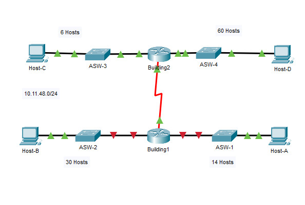
Part 1: Examine the Network Requirements
Part 2: Design the VLSM Addressing Scheme
Part 3: Assign IP Addresses to Devices and Verify Connectivity
In this activity, you are given a /24 network address to use to design a VLSM addressing scheme. Based on a set of requirements, you will assign subnets and addressing, configure devices and verify connectivity.
You will subnet the network address 10.11.48.0/24. The network has the following requirements:
How many subnets are needed in the network topology? 5
a. Which subnet mask will accommodate the number of IP addresses required for ASW-1?
255.255.255.240/28
How many usable host addresses will this subnet support?
14 (10.11.48.97 - 10.11.48.110)
b. Which subnet mask will accommodate the number of IP addresses required for ASW-2?
255.255.255.224 /27
How many usable host addresses will this subnet support?
30 (10.11.48.65 - 10.11.48.94)
c. Which subnet mask will accommodate the number of IP addresses required for ASW-3?
255.255.255.248 /29
How many usable host addresses will this subnet support?
6 (10.11.48.113 - 10.11.48.118)
d. Which subnet mask will accommodate the number of IP addresses required for ASW-4?
255.255.255.192 /26
How many usable host addresses will this subnet support?
62 (10.11.48.1 - 10.11.48.62)
e. Which subnet mask will accommodate the number of IP addresses required for the connection between Building1 and Building2?
255.255.255.252/30
a. Use the first subnet to accommodate the largest LAN.
b. Use the second subnet to accommodate the second largest LAN.
c. Use the third subnet to accommodate the third largest LAN.
d. Use the fourth subnet to accommodate the fourth largest LAN.
e. Use the fifth subnet to accommodate the connection between Building1 and Building2.
Complete the Subnet Table, listing the subnet descriptions (e.g. ASW-1 LAN), number of hosts needed, then network address for the subnet, the first usable host address, and the broadcast address. Repeat until all addresses are listed.
Subnet Table
| Subnet Description | Number of Hosts Needed | Network Address/CIDR | First Usable Host Address | Last Usable Host Address | Broadcast Address |
|---|---|---|---|---|---|
| Host-D LAN | 60 | 10.11.48.0/26 | 10.11.48.1 | 10.11.48.62 | 10.11.48.63 |
| Host-B LAN | 30 | 10.11.48.64/27 | 10.11.48.65 | 10.11.48.94 | 10.11.48.95 |
| Host-A LAN | 14 | 10.11.48.96/28 | 10.11.48.97 | 10.11.48.110 | 10.11.48.111 |
| Host-C LAN | 6 | 10.11.48.112/29 | 10.11.48.113 | 10.11.48.118 | 10.11.48.119 |
| WAN Link | 2 | 10.11.48.120/30 | 10.11.48.121 | 10.11.48.122 | 10.11.48.123 |
a. Assign the first usable IP addresses to Building1 for the two LAN links and the WAN link.
b. Assign the first usable IP addresses to Building2 for the two LAN links. Assign the last usable IP address for the WAN link.
c. Assign the second usable IP addresses to the switches.
d. Assign the last usable IP addresses to the hosts.
Most of the IP addressing is already configured on this network. Implement the following steps to complete the addressing configuration.
You can only verify connectivity from Building1, ASW-3, and Host-D. However, you should be able to ping every IP address listed in the Addressing Table.
en conf t int g0/0 ip add 10.11.48.97 255.255.255.240 no shut int g0/1 ip add 10.11.48.65 255.255.255.224 no shut
en conf t int vlan 1 ip add 10.11.48.114 255.255.255.248 no shut ip def 10.11.48.113
IP Address: 10.11.48.62
Subnet Mask: 255.255.255.192
Default Gateway: 10.11.48.1